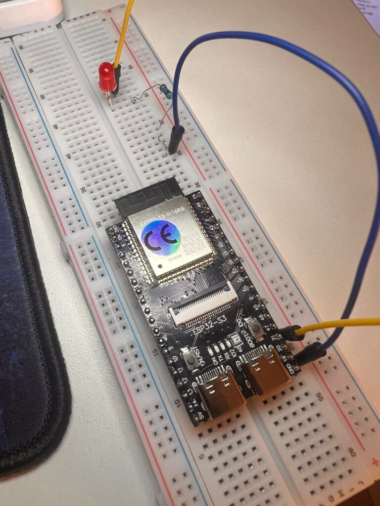
Introduction to my ESP32 LED blink project
I recently started learning embedded systems and robotics using an ESP32-S3 starter kit and MicroPython.
My first project was a classic ESP32 LED blink — making a single LED turn on and off. Although it sounds simple, it turned out to be
a valuable introduction to how hardware and software interact.
The Goal
The objective of this project was:
- Connect an LED to the ESP32
- Write a simple program
- Make the LED turn ON and OFF repeatedly
Components Used
- ESP32-S3 board
- USB cable (for power and programming)
- LED
- Resistor
- Breadboard or extension board
- Jumper wires
Understanding the Circuit
To light an LED, you need a complete electrical loop:
GPIO → LED → Resistor → GND- GPIO provides controlled power
- The LED emits light when current flows
- The resistor limits current to prevent damage
- GND completes the circuit
The ESP32 LED blink code
Here is the MicroPython code used:
from machine import Pin
import time

led = Pin(4, Pin.OUT)

while True:
    led.value(1)
    time.sleep(0.5)
    led.value(0)
    time.sleep(0.5)
This program continuously turns the LED ON and OFF every half second.
Challenges Faced
1. Running Code in the Wrong Environment
Initially, I tried running the code using standard Python on my computer, which resulted in:
ModuleNotFoundError: No module named 'machine'This happened because MicroPython code must run on the ESP32, not on a regular Python interpreter.
2. Confusion Between Arduino and MicroPython
I switched between Arduino IDE and Thonny, which caused confusion. Each uses a different programming language and workflow.
Choosing one environment and sticking with it resolved this issue.
3. Breadboard Misunderstanding
At first, I did not understand how breadboard connections work. The key realization was:
- Rows are connected horizontally
- The center gap separates the two sides
My initial wiring did not form a complete circuit.
4. Unstable Connections
At one point, the LED only turned on when I manually touched wires together.
This indicated that the circuit worked, but the connections were not properly secured.
5. Invalid GPIO Pins
Using certain pins resulted in errors such as:
ValueError: invalid pinThis showed that not all GPIO pins are available or usable on every ESP32 board.
6. Physical Layout Constraints
The ESP32 board covered many breadboard rows, limiting access to certain pins.
I had to adjust my wiring and choose accessible GPIO pins.
The Breakthrough
The project worked when I:
- Used a valid GPIO pin
- Connected the LED correctly:
- Long leg to GPIO
- Short leg to resistor and GND
- Ensured all connections were firm and properly placed
The LED finally blinked as expected, and my first ESP32 LED blink was working.
Key Learnings
This project helped me understand:
- How GPIO pins control hardware
- The importance of GND in completing a circuit
- How current flows in a loop
- Why resistors are necessary
- The need for alignment between software and hardware
Conclusion
Although simple, this ESP32 LED blink project provided a strong foundation in embedded systems.
It highlighted the importance of careful wiring, correct configuration, and systematic debugging. Next, I took on a bigger challenge in my ESP32-S3 10-LED flowing light project.
Next Steps
- Control the LED using a button
- Read input from sensors
- Connect the ESP32 to WiFi
Advice for Beginners
- Focus on one tool at a time
- Test small parts of the system incrementally
- Expect errors and use them as learning opportunities
- Pay close attention to wiring and connections
This project marks the beginning of my journey into embedded systems and robotics. If you are planning your own ESP32 LED blink, my biggest tip is to test each connection in small steps instead of wiring everything at once. Double-check that your chosen GPIO pin is actually usable, keep your ground and power rails clear, and read the error messages carefully — most of them point straight to the problem. A simple blinking LED may look basic, but it teaches the exact debugging habits you will rely on for every embedded project that follows.